8031 "base 1" board
A question, a problem or a suggestion, don't hesitate : a little email
A first processor board with:
- 8031 (or 40 pins compatible controller),
- 8 à 32 ko of EPROM + 8 à 32 ko of RAM,
- Outputs to LCD display , extension,...
Very useful for software tests because (due to the GAL configuration) the program memory is mapped into the external data memory. So a program loaded in the external data memory (with the assembler of the electronic tools for example) may be executed (and debugged) as a standard program.
Will be later replaced by a board using the new connectors pinout.
8031 "base 1" board
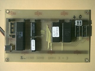
A picture of the board (sized 100 mm by 160 mm).
Schematic
In the future, I will use a derivative of the 8031 "base 2" board to have more standardized boards (connectors of the extension boards).
PCB
The PCB of the processor board.
Click on the picture to display the full resolution PCB (107 ko).
It's a 6.35 by 4 inches board (160 x 100 mm) at 600 dpi resolution.
Component side
Take care to the memories configuration and use, if necessary, the adequate resistors. With the scheme you will find easily the place of the different components.
Here the source and binary file for the GAL (1ko) for 8ko of EPROM and 8ko of RAM (max) or here for 8ko of EPROM and 32 ko of RAM.
Solder side
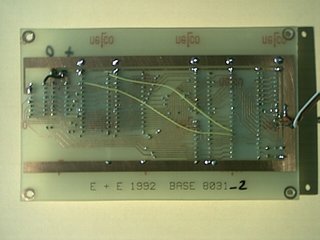
The yellow wires modification is required to use a 32 ko RAM. She is not needed for the aquarium controller application.
The other modification (dark wire) is no longer required with this PCB version (was required to use a backlighted display).