Stepper motor interface
A question, a problem or a suggestion, don't hesitate : a little email
Stepper motor interface
An unipolar stepper motor interface (with 5 or 6 wires) with 2 end-of-course switches.
Schematic

The avaliable current is limited by the power transistors (BUZ11) and the protection diodes (1N4007).
A fuse potects wholethe power unit.
Two end-of-course contacts can be connected.
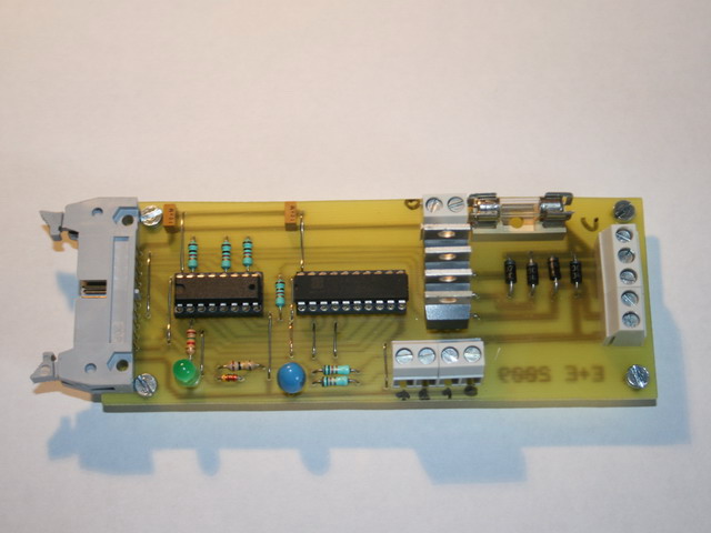
PCB
The PCB of the board.
Click on the picture to display the full resolution PCB (56 ko).
It is a 5 by 2 inches board at 600 dpi resolution.
Component side
The place of the different components of the board.
14 straps to avoid a double sided board.
For high currents, reinforce the printed circuit trace with solder for the high power area.
Application
All is controled through the Peri1 interface.
You will find here (22 ko), a test program in VC6.0 using the USB->Peri1 interface with wave, full and half stepping modes.