Test board for 18F4550 PIC
A question, a problem or a suggestion, don't hesitate : a little email
A test board for PIC 18F4550 built by a friend.
Can be directly connected to a Labdec Breadboard to realize quick experiments.
General view
This is the V01 version of my development board from icsp port or USB bus (bootloader like).
Schematic
This scheme is a direct application from Microchip's data sheets.
In the bootloader case, you must precisely use a 20 MHz quartz (isn't ?  ).
).
The long connector on the bottom of the board allows the connection with a Labdec development breadboard.
PCB
Component side.
The file Carte PIC 18F4550 V01.LYT (60 ko) has been developed with ARES from PROTEUS, 5.2 version. Those having this software will be able to modify the PCB.
For the others, as this is a 2 faces PCB, I have included the to sides in GIF files with the maximum resolution.
PCB
Solder side.
Finished board
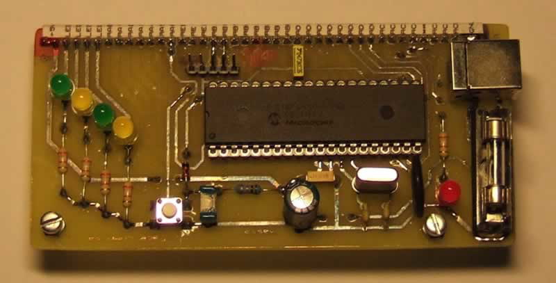
On the connector, you will find all the pins of the 18F4550, including the supply lines and the USB signals from the PC. Take care when using it.
The 4 leds on the right are optional for testing and can be omitted.
The push-button is for the reset of the PIC.
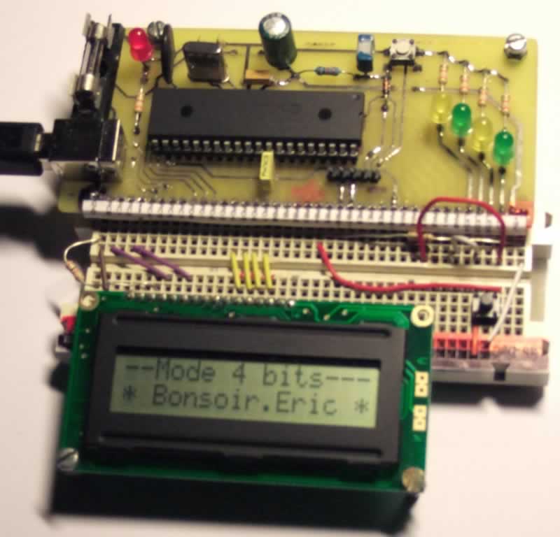
Use example of this board
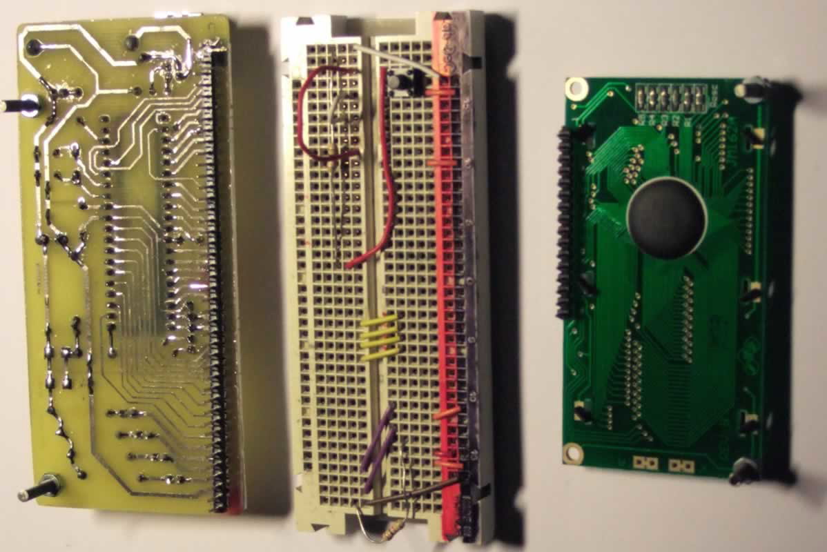
Board test with an LCD module.
Actually, for the bootloader programming, I use a push-button and a resistor for the RB4 pin on the Labdec board.