Electronic thermostat
A question, a problem or a suggestion, don't hesitate : a little email
Project aim
A thermostat to accurately trim the house temperature.
Ready for software extension to manage the temperature with a digital clock.
The old one
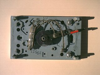
On the old mechanic thermostat, the output is on when a mercury drop within a glass bulb straps the 2 wires connected to the boiler.
The bulb is on a spring (the spiral on the picture) which fold and unfold with the temperature making the bulb tilt on the left or in the right side.
The new one (opened)
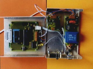
The new one have been built is a bow with 2 "U" parts (RETEX "Minibox" RM-11).
The bottom (on the right of the picture) carries the power supply, the switch and the thermometer.
The top (on the left) carries the display/keyboard and the micro-controller.
The top
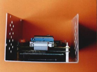
By the side, you can see :
- The display/keyboard board,
- The micro-controller board.
The 2 boards are mounted back to back, the flat wire between the 2.
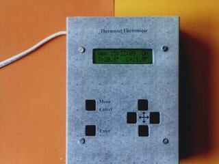
The front face
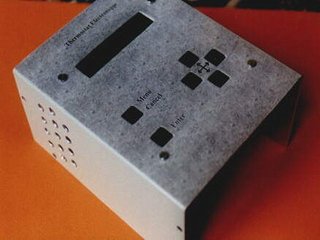
I have made the front face with a sticky laser printable plastic film. Some warnish protects the film and gives a bright aspect.
Click here (15 ko) to have a white film on which you can add your own background.
The keyboard have 6 keys : up, down, right, left, enter and menu/cancel.
General schematic
The block diagram shows the 5 boards and the different links between them.
In the schemes, the power supply and the switch are drawn together.
The reset switch may be omitted, and so the RS232 link only used to send to a PC the temperature measurements (for statistic purposes).
"Processor schematic(8031 "base 2" board)
the micro-controller part.
The RS232 link may be omitted.
Click here to have details on the processor board (PCB, wirering and pictures).
6 key keyboard/display
The display/keyboard board.
You can use a standard display or a back-lighted one.
Click here to have details on the board (PCB, wireing and pictures).
I2C board
The board with the digital thermometer (DS1621) and a clock (PCF8583).
The PCF8583 RAM allows a clean power up even after power cuts.
Switch/power supply
The power supply (12V and regulated 5V) and the switch. You can also use a standard 12V supply block (keeping the 5V regulation).
These 2 boards are connected with the supply lines (directly or through the boiler) and all adequate insulations must be used.
PCB
The PCB for the 5 boards. Click on the picture to display the full resolution PCB (229 ko) or here to downoad it.
To avoid a double sided board, some connections must be realised with wires on the solder side.
It's a 8 by 6 inches board at a 600 dpi resolution.
Component side
The place of the different components.
The circuits are easily identified with the schemes.
Software
The software, its source and its documentation in 1.1 version : THERV11.ZIP (14ko) (the binary file is in intel-32 format).
This first version is a basic thermostat with an adjustable hysteresis and monitoring through the serial link.