Installation and test of a RAVAR MOD4 module
A question, a problem or a suggestion, don't hesitate : a little email
The module
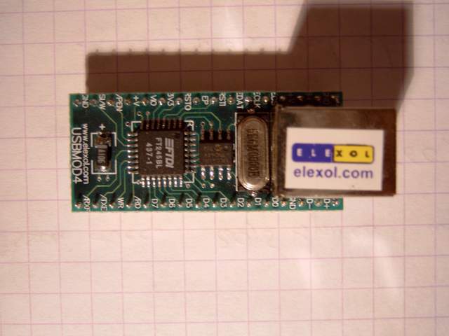
The RAVAR MOD4 module is an USB interface to a 8 bits parallel port.
It use a FT245BM and doesn't need any additional active or passive component.
It is easily interfaced to a microprocessor, microcontroler or directly with an application through the "bit bang mode".
The installation
The installation needs to wake up the module. To do this, connect the 9 and 10 pins ("EP" for Enumeration Power and "RSTO" for ReSeT Out).
After enumeration, XP asks to install the driver. I use the "D2XX CDM 2.00.00" driver witch combines a "Direct driver" and a "Virtual COM Port" driver.
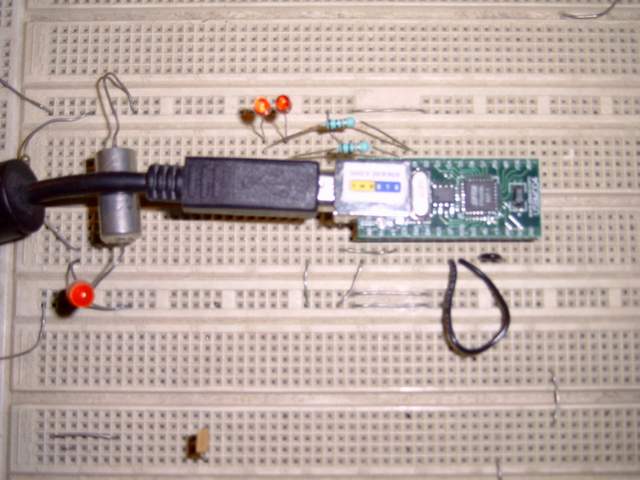
Test schematic
A simple schematic to test the module. It is based on 2 connection en the module :
- The above needed for enumeration,
- An other one needed to supply the inputs/outputs of the module (connection between 12 and 13 pins).
Two leds enable a visual test of the outputs (D0 and D1).
Test program
The test program (VC source and executable downloadable here (20ko)) with 3 steps :
- Slow blinking test of the leds (eye seeable),
- Fast blinking of the leds witch needs an oscilloscope (see below),
- Inputs test of the module where you can see the input read by the PC changing when you ground one of the RAVAR inputs (D2 to D7).
Output signals in fast blinking mode
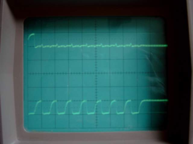
The fast blinking test needs an oscilloscope.
D1 output is used to trigger the scope and the D0 output is switching very fast (about 1 µs per state).