Coils for switching power supplies
A question, a problem or a suggestion, don't hesitate : a little email
Some tests on coils for switching power supplies :
- Calculations,
- Test apparatus,
- Results of some measurements.
Coils for switching power supplies
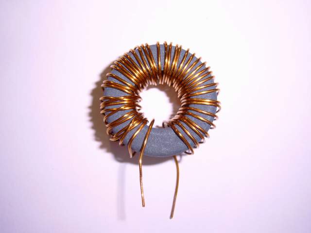
A typical coil for switching power supply :
- Enamelled copper wire around a ring core.
Two main parameters :
- Inductance (in Henry),
- Saturation current (in Ampere).
Calculations
Example (toroid of the above picture) :
Manufacturer data (2P80 material, iron powder, size 26.5x14.9x10.7 with 46 turns) : Al=94 nH, Bsat=1.4 T, le=0.062m, µ0=1.257 10-6 H/m, µi=90
L=94*46*46=199 µH
Isat=(1,4*0.062)/(1.257 10-6*90*46)=17 A
Measurement principle
A voltage step is applied on a L/R network.
Vb voltage is given by : Vb(t)=Va.(1-exp(-R.t/L))
so dV/dt=Va.R/L.exp(-R.t/L)
Using the slope measured with an oscilloscope, the inductance of the coil is :
L=(Va.R)/(dV/dt)(0)
Measurement circuit
A simple power switcher feeded with a signal generator.
For a more accurate measurement, replace the TIP42C with a power MOSFET (smaller ON resistance).
The diode may be omitted if the power transistor can handle the negative peak voltage during off switching.
Measurement circuit
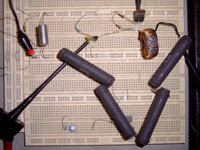
Circuit enough simple for an breadboard.
Resistor is built using the 4 black power resistors in series.
Result of a measurement
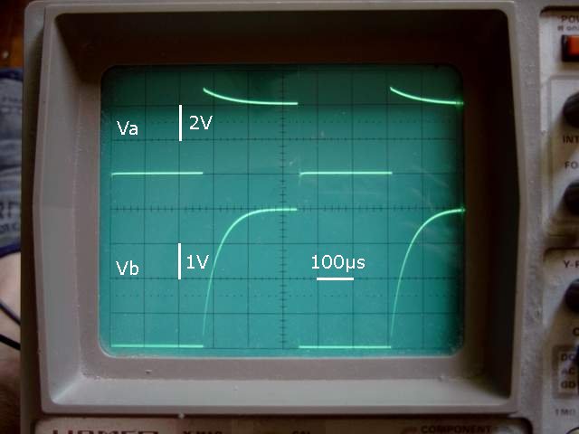
Test of the above coil with a 6 Ohm resistor.
Va drop is due to TIP42C ON resistance. The small step at the beginning is due to the inductive part of the power resistors (to be avoided).
Slope measured : 120000 V/s (0,6 V in 5 µs)
So, inductance of the coil is :
L=(4,6 V*6 Ohm)/(120000 V/s)=230 µH
for a theoretical value of 200 µH
Another result
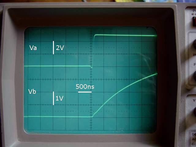
Test of a coil using 3F3 material.
On the top, a test using a small current (R=100 Ohm, Va=5 V) for a measured value for the coil of 250 µH.
On the bottom, the same coil but measured using a higher current (R=6,6 Ohm, Va=4,8 V).
Current evolution is normal until Vb reaches slightly more than 1 Volt, so a 200 mA current. This is the point where the coil saturate with a rapid decrease of the inductance and a higher slew rate of the current.
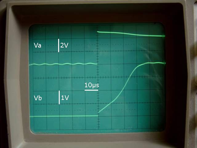
Result on a switching power supply
Comparison of 2 coils for the switching power supply of the electronic thermostat (LM2575-5 used as a 12 V->5 V converter).
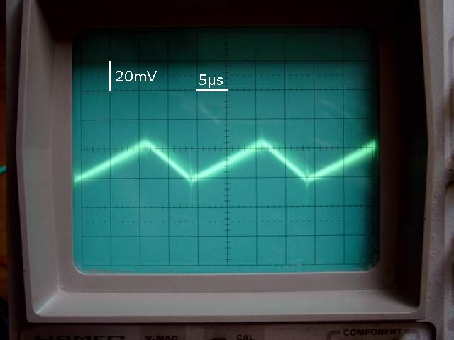
On top, the output voltage using the above iron powder coil with a 6,6 Ohm supply load. Ripple is about 25 mV.
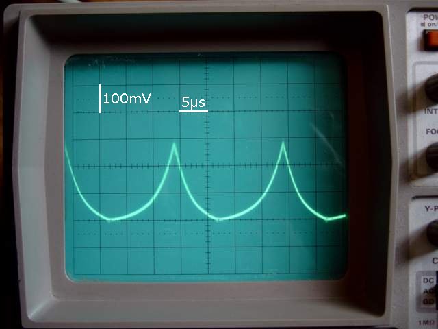
On bottom, the output of the same power supply and with same load but using a 3F3 based coil with the same inductance. Ripple reach now 300 mV, unacceptable value even for digital circuits. Fortunately the peak voltage is regulated by the the LM2575-5 at about 4,9 V.
At last, during calculations or tests, don't forget that the peak current in the coil is greater than the average current in the load (often twice as much).