Robot 2, electronics
A question, a problem or a suggestion, don't hesitate : a little email
The electronic boards
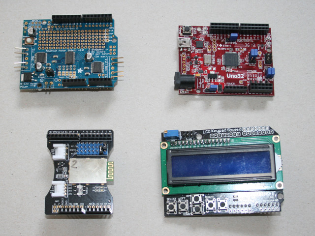
The robot requires one Arduino board and 3 shields. I have used (from bottom to top of the stack) :
- A chipKIT UNO32 board from Digilent (with regulator, PIN 10 as a digital I/O, SPI master, A4 and A5 as an I2C interface),
- A "Motor shield" from Adafruit (3.3 V I/O configuration, this shield supplying the UNO32 board),
- A "Bluetooth shield" from Seeedstudio (BT_Tx=D0 et BT_Rx=D1),
- A "LCDKeypad shield" from DFRobot (modified for the UNO32 board as described here).
The "Motor shield"
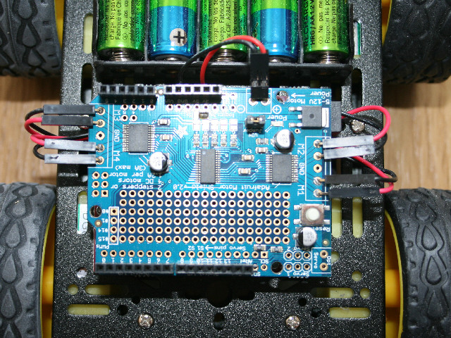
The power comming from the switch arrives on this board which supplies all the robot (with the jumper as shown on the picture).
The board is configured for 3.3 V I/O with a small ball of solder (top and middle of the picture).
The motors are connected to the board as they are physically on the robot (on bottom right, the motor which is on the bottom right,...). Take care of the red and black wires positions so that the 4 motors turn in the same direction).
The "Bluetooth shield"
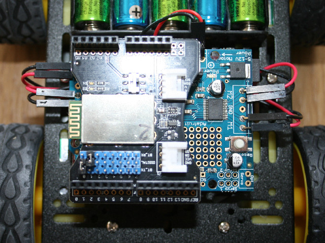
The Bluetooth module is configured with :
- BT_Tx connected to D0 and BT_Rx connected to D1 (so a downloading of the software into the Arduino board only possible when the Bluetooth shield is removed),
- The switch so that the BTStatus output goes to the A1 of the Arduino board.
The "LCDKeypad shield"
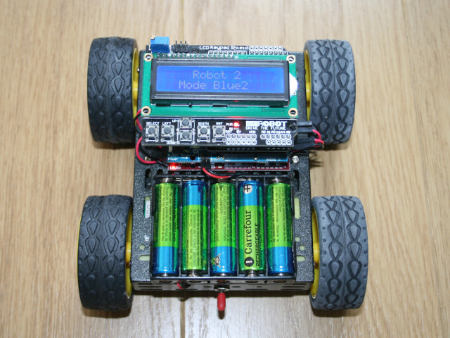
The display I have used for the tests and now is only used to display a message during the boot and after the status of the connection between the Bluetooth and the phone.
Ask me if you need a compiled software avoiding to implement this board.