Aquarium controller
A question, a problem or a suggestion, don't hesitate : a little email
Project aim
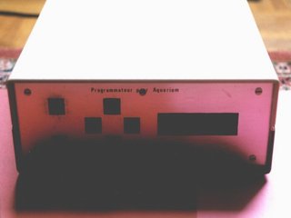
A controller with 4 outputs to manage lightening, warming, oxygenating and filtering of an aquarium.
Minute per minute (and day per day) operating program of each output.
Opened box picture
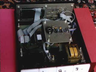
All the electronic parts are in a plastic box. From front to back :
- The 4 outputs near the switch/supply board,
- The processor board with the I2C clock board on it,
- The display/keyboard board.
General schematic
The block diagram shows the 4 boards and the different links between them.
In the schematic, the clock and the display/keyboard are drawn together.
All boards, except the processor one, have been done with prototype boards.
Processor board
(8031 "base 1" board)
The microcontroler board.
For this project and in this version, I use a board with 8k*8 E2PROM, a 2k*2 RAM and a 6 MHz processor.
Click here to have details on the processor board (PCB, wiring and pictures).
Switch and supply
A simple supply and 4 relays.
I had the DS1634 in my stock and recommend to use the same switch that I have used for the thermostat project (replace the 4 DS1634 and the 4011).
The inputs must be connected to the processor board through the "port" output.
Keyboard, display and clock
The display is directly connected to the adequate processor board output.
The clock is connected to the I2C bus and to the "port" output of the processor board.
The keyboard uses the "extension" output.
Software
The software and its documentation in 2.1 release :
POISSO21.ZIP (9ko) (the binary file is in intel-32 format).