GPIO Port for Raspberry PI
A question, a problem or a suggestion, don't hesitate : a little email
GPIO Port use with the Raspberry PI :
- Pinout and test device,
- Test using Python,
- Configuration and test in C/C++.
Pinout and test device
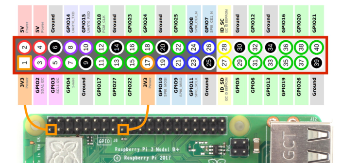
On the left, you will find the pinout of the standard 40 pins connector (since the Raspberry 2).
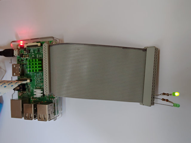
For the tests, I have used two leds on which we limit the current with a 390 Ohm resistor :
- One between pin 33 (GPIO13, + side) and pin 34 (Ground, - side),
- One between pin 35 (GPIO19, + side) and pin 39 (Ground, - side).
Test using Python
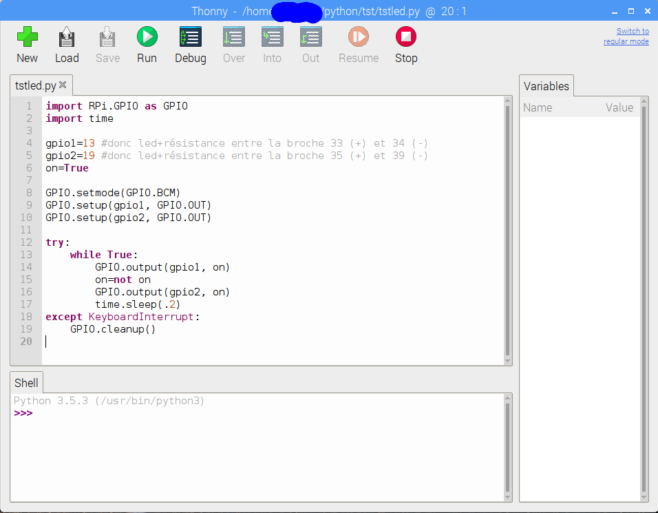
Python3 test :
- The Python3 driver is installed automatically with Buster,
- (Here), the source of the program which makes the two leds to flash alternately.
Configuration and test in C/C++

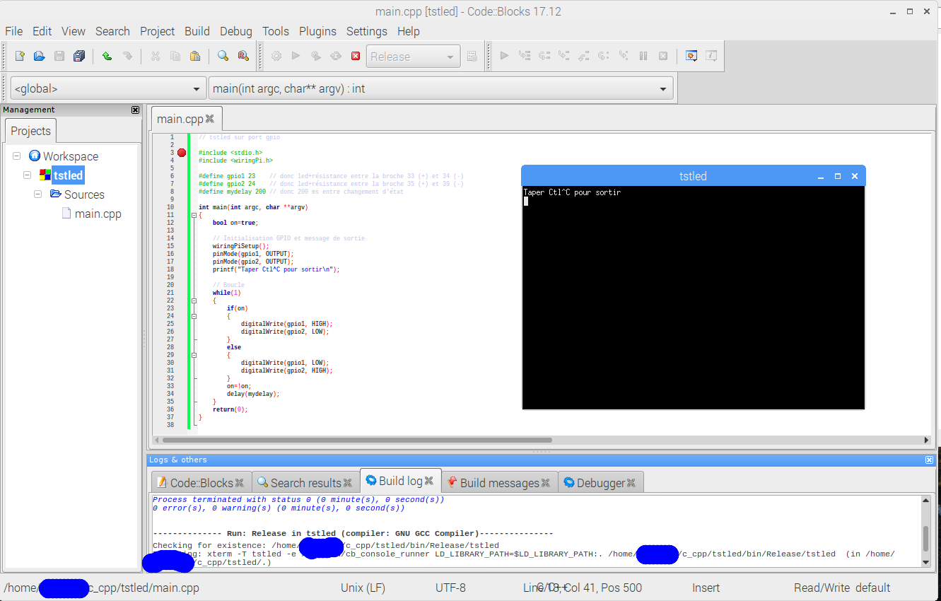

For C/C++, I have used the WiringPi library which installed automatically with Buster.
You just need to :
- Include the libray description file (#include <wiringPi.h>;),
- Make the link with the library (see on the left).
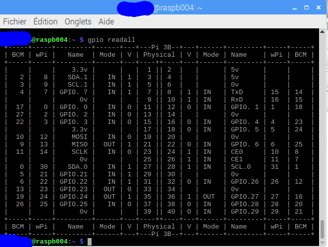
WiringPi uses its own pins numbering. The gpio readall command will give you the connection for the Raspberry you are using (see on the left).
You will find there the source of the program.
The library is rather fast. The last picture shows the signal on one of the leds with the delay(mydelay) instruction removed. We are at 8 MHz with the two leds and a Raspberry 3B !